[!WARNING]
### MOLD CRITICAL WINDOW: 24–48 HOURS POST-FLOOD
• IICRC S500 Section 4 classifies any porous assembly (carpet face + primary backing + padding + subfloor) that remains saturated beyond 48 hours at temperatures above 68°F (20°C) as presenting active microbial colonization risk.
• Category 1 (clean water) losses that are not dried within 24–48 hours escalate to Category 3 biological contamination as mold spore counts exceed 1,000 CFU/m³ and gram-negative bacteria proliferate in standing moisture.
• Deploying commercial-grade air movers within 4 hours of water intrusion detection is the single highest-use action available to restorers.
Water intrusion is not a cleaning problem. It is a drying science problem. Every hour carpet remains saturated past the 24-hour mark, the probability of mold colonization increases by a measurable, calculable margin. Yet the response in most residential water damage events still defaults to household box fans set on the floor — tools that deliver between 50 and 200 cubic feet per minute (CFM) of poorly directed air against a surface that requires 300 to 450 CFM per unit of focused boundary layer disruption to achieve meaningful evaporation.
Professional carpet air movers — axial or centrifugal turbines engineered specifically for structural drying — operate at fundamentally different physics. Understanding why they work, how to place them, and how to read the psychrometric data that confirms they are working is the difference between a carpet that returns to service in 36 hours and one that grows Aspergillus niger colonies beneath its backing within 72 hours.
This guide documents the complete IICRC S500-compliant structural drying protocol for carpet air movers: equipment physics, water damage classification, placement geometry, dehumidification pairing, moisture monitoring targets, electrical safety, and drying validation documentation.
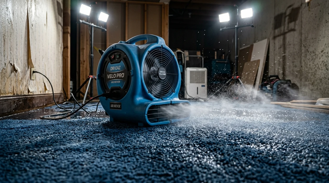
IICRC S500 water damage classification: what category and class determine your equipment count
The IICRC S500 Standard for Professional Water Damage Restoration defines two orthogonal classification axes that govern every equipment decision a restorer makes. Confusing category with class is a diagnostic error that leads to either under-drying (leaving pathogens) or over-drying (causing secondary damage through shrinkage or delamination).
Water category: contamination level
| Category | Source | Pathogen Risk | Drying Protocol |
|---|---|---|---|
| Category 1 | Clean municipal supply line break, toilet tank overflow, rainwater (before 24 hrs) | Minimal | Standard structural drying — air movers + dehumidification |
| Category 2 | Washing machine overflow with detergent, dishwasher discharge, mild toilet bowl overflow | Moderate | Enhanced extraction + drying + antimicrobial application |
| Category 3 | Sewage backup, rising floodwater, Category 1 loss aged beyond 48–72 hours | Severe | Carpet and pad removal mandatory in most protocols; structural drying of subfloor only |
Category escalation is time-dependent. A Category 1 clean-water loss that sits unaddressed for 48 hours becomes a Category 3 event due to microbial amplification in the saturated porous matrix. Homeowners often delay calling a restorer because the water "looks clean", which gives mold time to grow in the pad.
Water class: moisture load and penetration depth
| Class | Wet Material | Affected Area | Air Mover Ratio |
|---|---|---|---|
| Class 1 | Part of room — minimal absorption into walls, minimal pad saturation | < 5% of total flooring in space | 1 air mover per 50–70 sq ft |
| Class 2 | Entire room — carpet and pad saturated, minimal wall wicking above baseboard | Entire floor + 12–24 in. above baseboard | 1 air mover per 40–50 sq ft |
| Class 3 | Walls and ceiling saturated from above — overhead intrusion | Floor + walls + ceiling assemblies | 1 air mover per 30–40 sq ft |
| Class 4 | Specialty drying — concrete, hardwood, plaster, dense materials with very low porosity | Sub-surface and structural assemblies | Specialty drying chambers + directed air |
For a standard residential carpet-over-pad Class 2 loss in a 200 sq ft bedroom, you need a minimum of 4 to 5 commercial air movers running simultaneously. Box fans from a hardware store cannot substitute for this equipment count.
Air mover physics: axial vs. centrifugal turbines
Not all air movers move air the same way. The two dominant mechanical designs — axial (propeller-type) and centrifugal (snail-shell scroll) — produce radically different airflow curves that make each appropriate for specific placement scenarios.
AXIAL vs. CENTRIFUGAL AIR MOVER — AIRFLOW CURVES:

  AXIAL (Open Propeller)          CENTRIFUGAL (Scroll Housing)
  -------------------------       ----------------------------
  CFM Output: 2,400–3,800         CFM Output: 1,800–2,600
  Static Pressure: Low (< 1 in)   Static Pressure: High (1–4 in WC)
  Noise Level: High               Noise Level: Moderate

  Best Use: Open floor             Best Use: Wall cavities,
  evaporation, high-              confined drying chambers,
  velocity surface sweep          under cabinets, crawl spaces

         Airflow vs. Static Pressure:
         ┌─────────────────────────────┐
    CFM  │ Axial: ▓▓▓▓▓▓░░░░           │
         │ Centrifugal: ▒▒▒▒▒▒▒▒▓▓▓   │
         │        ─────────────────    │
         │             Static Pressure →│
         └─────────────────────────────┘
Axial air movers (e.g., XPOWER P-630A, B-Air BP-1) move very high volumes of air at low static pressure. They excel at carpet surface drying because they generate the high-velocity boundary layer disruption needed to pull water vapor off wet pile fibers and push it into the ambient air column where the dehumidifier can capture it.
Centrifugal air movers (e.g., B-Air Vent 2 HP, Dri-Eaz F351) use an impeller inside a volute housing to compress and accelerate air through a directional snout. This design tolerates back-pressure, making centrifugal units the correct choice for wall cavity injection, subfloor drying chambers, and any application where the air must travel through a restricted orifice before reaching the drying surface.
For carpet-over-pad drying, axial units are the standard workhorse. Centrifugal units serve primarily when engineered hardwood or floating subfloor assemblies beneath the carpet need separate treatment.
AXIAL AIR MOVER — INTERNAL AIRFOIL GEOMETRY:

  ┌─────────────────────────────────────────────┐
  │   Motor           Impeller Blades           │
  │   Housing    ┌──────────────────┐           │
  │   [===]      │  Blade Pitch:    │  → → → → │ AIR
  │   [===] ───→ │  17–23° optimal  │  → → → → │ OUTPUT
  │   [===]      │  for carpet CFM  │  → → → → │
  │              └──────────────────┘           │
  │                                             │
  │  At 17° pitch: lower CFM, lower noise       │
  │  At 23° pitch: higher CFM, higher amp draw  │
  └─────────────────────────────────────────────┘
The airfoil pitch angle is the key performance variable in axial units. Blades pitched between 17° and 23° from the plane of rotation optimize carpet-drying CFM output within residential electrical circuit constraints (typically 15 or 20 amp circuits at 120V). Pitching beyond 23° increases CFM but proportionally increases amperage draw, creating circuit-loading conflicts when multiple units share one breaker.
Psychrometry: understanding what the air must carry out
Structural drying succeeds when the air inside the drying chamber carries moisture vapor from wet surfaces to the dehumidifier's refrigerant coil. This transfer is governed by psychrometric principles — the thermodynamics of moist air behavior.
Grains per pound (GPP) is the primary metric. One grain equals 1/7,000 of a pound. At 70°F (21°C) and 50% relative humidity, ambient air contains approximately 54 GPP of water vapor. Saturated carpet and pad with 25% moisture content (wet weight basis) can release thousands of GPP into the closed drying chamber over a 24-hour period.
PSYCHROMETRIC DRYING PROCESS — CLOSED CHAMBER MODEL:

  ┌─────────────────────────────────────────────────────┐
  │         STRUCTURAL DRYING CHAMBER                   │
  │                                                     │
  │  Wet Carpet → [Air Mover] → Air Velocity ↑         │
  │  Wet Pad   →  Surface Turbulence ↑                  │
  │              Boundary Layer Disruption ↑            │
  │              Vapor Pressure Differential ↑          │
  │                    ↓                                │
  │          [Humid Air: 70°F / 85% RH / 140 GPP]      │
  │                    ↓                                │
  │          [LGR Dehumidifier — Refrigerant Coil]      │
  │          Coil Temp: 40°F (below dew point)          │
  │          Condensate drains at 60–80 pints/day       │
  │                    ↓                                │
  │          [Dry Air: 70°F / 30% RH / 32 GPP]         │
  │          Returned to chamber → repeats cycle         │
  └─────────────────────────────────────────────────────┘
Vapor pressure differential drives evaporation. The vapor pressure of water at the wet carpet surface exceeds the vapor pressure of the ambient drying air. This differential is the engine of evaporative drying. Air movers accelerate this process by constantly sweeping away the vapor-saturated boundary layer immediately above the wet surface and replacing it with drier ambient air, maintaining a steep and persistent vapor pressure gradient.
Dew point is the temperature at which ambient air reaches 100% relative humidity and condensation begins. If the drying chamber temperature drops below the dew point of the humid internal air, moisture re-deposits onto cold surfaces rather than being captured by the dehumidifier. Maintaining chamber air temperature above 70°F (21°C) during active drying is mandatory for efficient vapor removal.
Evaporative capacity calculation for a standard 200 sq ft Class 2 bedroom:
ESTIMATING MOISTURE LOAD (simplified field method):

  Carpet face weight: 40 oz/yd² → ~0.27 lbs/sq ft dry weight
  Estimated moisture content at saturation: 25% (wet basis)
  Moisture held per sq ft: 0.27 × 0.25 = 0.068 lbs
  Total carpet moisture (200 sq ft): 200 × 0.068 = 13.5 lbs = ~94,500 grains

  Pad moisture (rebond, 7/16 in × 6 lb density):
  Estimated saturation: 0.05 lbs/sq ft
  Total pad moisture (200 sq ft): 200 × 0.05 = 10 lbs = ~70,000 grains

  Total moisture to remove: ~164,500 grains ≈ 23.5 lbs ≈ 28 US pints

  LGR dehumidifier at 70°F / 60% RH: ~70 pints/day removal capacity
  Estimated gross drying time (carpet + pad only): 28 / 70 = 0.40 days ≈ 9.5 hours
  Real-world factor (wall absorption, vapor lock, inefficiency): × 3 to 4
  Realistic drying window: 24–36 hours with correct equipment count
This calculation illustrates why hitting the 24-hour mold window is achievable with professional equipment — but impossible with household fans that cannot establish the boundary layer disruption or the dehumidification capacity needed to maintain vapor pressure differential.
Equipment placement geometry: the 45-degree displacement theory
The six-to-eight air mover displacement theory is the industry-standard placement protocol derived from IICRC S500 structural drying field research. Each unit must displace between six and eight feet of airflow across the floor before the next unit accepts the airstream and adds velocity.
IICRC S500 — 6-8 AIR MOVER DISPLACEMENT PROTOCOL
Top-down floor plan view (20×10 ft room, Class 2):

  Wall ─────────────────────────────────── Wall
  │                                            │
  │  [AM1]→→→→→→→→[AM2]→→→→→→→→[AM3]          │
  │  45°          45°           45°            │
  │                                            │
  │  ↑            ↑             ↑              │
  │                                            │
  │  [AM4]←←←←←←←[AM5]←←←←←←←[AM6]          │
  │  45°          45°           45°            │
  │                                            │
  Wall ─────────────────────────────────── Wall

  AM = Air Mover, pointed at 45° angle to baseboard
  Spacing: 6–8 linear feet between units along wall
  Dehumidifier: centered or in adjacent room with door cracked
The 45-degree wall angle is not arbitrary. Directing the air mover snout at 45 degrees to the baseboard creates a helical airflow pattern that sweeps across the entire floor surface more efficiently than straight-line alignment. A unit aimed directly perpendicular to the wall creates a dead air pocket in the far corners. A unit aimed parallel to the wall wastes velocity on wall surfaces rather than floor materials.
Drying chamber creation seals the affected space to prevent the humid interior air from venting into other rooms. Close all doors and windows. Use plastic sheeting to isolate adjacent rooms if necessary. A sealed drying chamber concentrates dehumidifier capacity on the target moisture load and prevents recirculation of unconditioned exterior air that may carry higher absolute humidity.
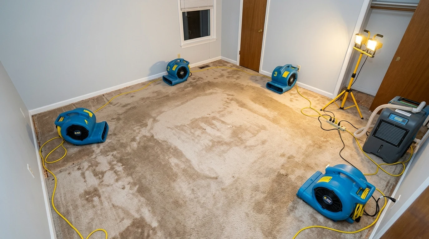
Critical placement errors:
- Units aimed at walls rather than floors. Wall surfaces dry faster than thick carpet-pad assemblies; misdirected air movers dry the paint while the pad remains saturated.
- Insufficient unit count for room square footage. One or two air movers in a 300 sq ft room moves air but cannot achieve the boundary layer disruption density needed to hit the 24-hour mold window.
- Stacking units. Placing one air mover directly on top of another doubles noise but reduces effective floor coverage because the upper unit's airstream misses the carpet surface entirely.
- Blocking dehumidifier exhaust. If the dehumidifier's warm dry air outlet is blocked by furniture or positioned facing the wall, the dry air cannot circulate through the drying chamber.
Moisture monitoring: pin meters, thermo-hygrometers, and drying targets
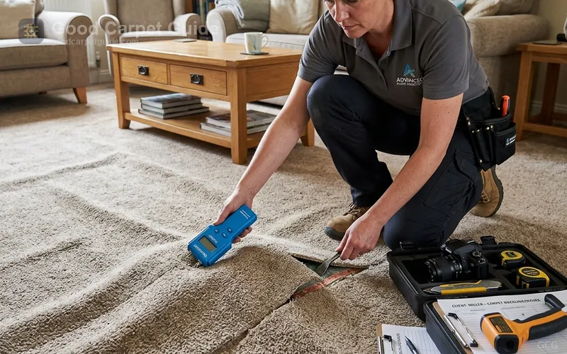
Equipment placement must be validated with objective moisture readings taken at multiple material layers. Visual inspection and tactile assessment cannot detect moisture content in carpet primary backing, pad, or subfloor at levels that support mold growth.
Pin-type moisture meter targets
| Material | Acceptable Dry Standard | Monitoring Frequency |
|---|---|---|
| Carpet face fibers | ≤ 15% moisture content (MC) | Every 4 hours during active drying |
| Primary backing (polypropylene or action bac) | ≤ 12% MC | Every 4 hours |
| Rebond or prime foam pad | ≤ 12% MC — pad must be physically extracted and tested separately | Before and after equipment placement |
| Wood subfloor (OSB or plywood) | ≤ 12% MC | Every 6–8 hours |
| Concrete subfloor | ≤ 4% MC or RH ≤ 75% (ASTM F2170) | 12-hour intervals |
The General Tools MMD4E pin moisture meter provides reliable readings in carpet at depths of 0.25 to 0.5 inches. Insert the pins perpendicular to the surface until they contact the primary backing plane, not just the face pile. Face pile moisture can read low while backing moisture remains dangerously raised due to slower capillary wicking rates in secondary backing jute or action-bac.
For subfloor readings, use a deeper-penetrating pin set or a hammer probe extension to reach the lower face of the plywood or OSB where moisture migrates from pad saturation contact.
Thermo-hygrometer readings and the drying curve
Track ambient temperature, relative humidity (RH), and GPP inside the drying chamber at 4-hour intervals. A functional drying chamber shows a characteristic curve:
IDEAL DRYING CHAMBER PSYCHROMETRIC CURVE (72-hour window):

  Hours:     0    4    8   12   18   24   30   36   48   72
  RH (%):   85   82   78   72   65   58   50   44   38   35
  GPP:      140  132  120  108   88   72   54   46   40   36
  Temp (°F): 70   71   72   72   72   72   72   72   72   72

  ↓ GPP decreasing consistently = dehumidifier removing moisture ✓
  ─ Temperature stable = drying chamber energy balance maintained ✓
  If GPP plateaus or rises = check dehumidifier drainage, add unit, check for hidden pockets
If the GPP reading plateaus or rises after 12 hours, the drying chamber has a moisture source the equipment cannot overcome. Common hidden sources include wet insulation inside wall cavities, saturated subfloor through-holes, or an active plumbing leak that was not fully repaired before equipment deployment.
LGR vs. conventional dehumidifier: grain removal capacity matters
Standard refrigerant dehumidifiers reach their minimum removal capacity floor at ambient GPP readings around 45 to 55 GPP (approximately 60% RH at 70°F). Below this threshold, the refrigerant coil cannot condense sufficient moisture to sustain effective grain removal. In a well-sealed and actively dried chamber, GPP drops toward this floor in 18 to 24 hours — and a standard dehumidifier stalls.
Low-Grain Refrigerant (LGR) dehumidifiers use a heat exchanger pre-cooling stage that drops incoming air temperature before it reaches the primary refrigerant coil. This allows the coil to condense moisture at ambient GPP levels as low as 30 GPP — the critical zone where conventional units fail.
| Dehumidifier Type | AHAM Standard Removal Rate | Effective GPP Range | Best Application |
|---|---|---|---|
| Conventional Refrigerant | 20–45 pints/day (at 80°F/60% RH) | 55–200 GPP | Initial extraction phase, high-RH environments |
| LGR (Low-Grain Refrigerant) | 60–100+ pints/day (at 80°F/60% RH) | 30–200 GPP | Full drying cycle, final drying phase below 45 GPP |
| Desiccant Rotary | 30–80 pints/day regardless of temperature | Works at 20°F–120°F | Cold environments, crawl spaces, winter water losses |
AHAM (Association of Home Appliance Manufacturers) standard testing conditions are 80°F and 60% relative humidity. Always compare dehumidifier capacity at AHAM standard, not at inflated "max capacity" figures that some manufacturers report at 90°F / 90% RH — conditions rarely encountered in real drying chambers.
For the 200 sq ft Class 2 bedroom example, a single LGR unit rated at 70 pints/day at AHAM conditions provides sufficient grain removal capacity through the entire drying cycle, including the final low-GPP phase below 45 GPP where conventional units stall.
Electrical safety in wet environments: circuit loading and GFCI requirements
Running multiple high-amperage devices in a water-damaged space carries genuine electrocution risk. IICRC S500 and OSHA 29 CFR 1910.304 both mandate Ground Fault Circuit Interrupter (GFCI) protection for all electrical equipment used in wet or potentially wet environments during water damage restoration.
Circuit loading calculation — never exceed 80% of the breaker's rated amperage during continuous operation:
CIRCUIT LOAD SAFETY CALCULATION:

  Standard 15-amp circuit → Maximum safe continuous load: 15 × 0.80 = 12 amps
  Standard 20-amp circuit → Maximum safe continuous load: 20 × 0.80 = 16 amps

  Example: XPOWER P-630A (2.0 A per unit)
  On a 20-amp circuit: 16 amps ÷ 2.0 amps = 8 units maximum
  (BUT: always verify with actual nameplate amperage and account for motor startup surge)

  Example: hOmeLabs Dehumidifier (5.4 A at 645 W / 120V) + 5 air movers (10 A)
  Total: 15.4 A → exceeds 20-amp circuit limit (16 A safe threshold)
  Correct configuration: Dehumidifier on dedicated circuit + air movers on second circuit
GFCI protection must be applied either through GFCI-protected wall outlets (installed by an electrician before or as part of the restoration scope) or through portable GFCI adapters plugged into standard outlets before plugging in any restoration equipment. A portable GFCI unit trips at 5 milliamps of ground fault current — well below the 10 to 20 milliamp threshold for painful shock and the 100 to 300 milliamp threshold for ventricular fibrillation.
Do not plug restoration equipment directly into standard duplex outlets when visible water or moisture contamination is present in the electrical box vicinity. If water has reached within 12 inches of any outlet, panel, or junction box, engage a licensed electrician to verify circuit integrity before restoration equipment is energized.
IICRC S500 Section 13 drying documentation: the legal record
Professional water damage restoration is a liability-bearing activity. Every moisture reading, equipment placement decision, and drying time recorded during a loss becomes part of the legal chain of evidence if disputes arise over coverage, secondary damage claims, or mold liability.
IICRC S500 Section 13 specifies minimum documentation requirements:
IICRC S500 SECTION 13 — MINIMUM DRYING DOCUMENTATION RECORD:

  Job Record Required Fields:
  ├── Loss Date & Time
  ├── Discovery Date & Time (if different)
  ├── Initial Site Assessment: Category (1/2/3) and Class (1/2/3/4)
  ├── Water Source: Confirmed origin and stoppage verification
  ├── Initial Psychrometric Readings: Temp (°F), RH (%), GPP, Dew Point
  ├── Materials Affected: Type, construction, approximate square footage
  ├── Equipment Deployed: Make, model, serial number, placement location
  ├── Moisture Mapping: Daily moisture content readings (MC %) by material and location
  ├── Psychrometric Monitoring: 4-hour interval readings (Temp, RH, GPP)
  └── Final Drying Verification: MC readings at or below dry standard, signed by technician
A moisture map — a floor plan sketch with MC readings documented at 4-foot grid intervals — provides spatial evidence of drying progression. At project closeout, a final moisture map with readings at or below the IICRC S500 dry standard (carpet ≤ 15% MC, wood ≤ 12% MC) constitutes the primary evidence of a professionally completed structural drying project.
Without this documentation, a homeowner or insurer has no objective basis to verify that drying was complete. Incomplete drying records are the most frequent point of dispute in water damage restoration litigation.
Step-by-step protocol: from water discovery to drying completion
Executing a successful structural drying cycle requires a disciplined operational sequence that aligns water extraction, airflow setup, psychrometric monitoring, and final validation into four distinct phases.
Phase 1 — Immediate response (Hour 0–2)
Stop the water source. Photograph the loss from all angles before touching anything. Identify Category and Class using the IICRC S500 classification matrix above. Deploy the wet/dry vacuum immediately — extract all standing water from carpet, pad edges, and hard floor areas adjacent to carpet. Do not delay extraction to wait for drying equipment.
Remove furniture from the wet zone. Place aluminum foil or foam blocks under remaining furniture legs to prevent wood tannins from bleeding into carpet pile and creating permanent staining.
Phase 2 — Equipment deployment (Hour 2–4)
Position air movers per the 6-to-8 displacement geometry at 45-degree wall angle. Seal the drying chamber by closing all doors and windows. Deploy the dehumidifier in or adjacent to the affected space. Take initial psychrometric readings and record them in the job documentation log.
Verify GFCI protection on all circuits before energizing any equipment. Calculate total amperage load and confirm no circuit exceeds 80% of rated capacity.
Phase 3 — Active monitoring (Hours 4–48)
Take psychrometric readings every 4 hours. Take material moisture content readings at the same intervals, documenting values on the moisture map. Plot the GPP curve — it should decline consistently. If GPP plateaus or rises after the 8-hour mark, investigate for hidden moisture pockets.
For deep pad saturation, consider carefully detaching carpet at a seam or along a wall and folding it back to expose the pad directly to air mover airflow. This is standard procedure in Class 2 losses when pad thickness exceeds 7/16 inch or pad density exceeds 8 lb/cubic foot — both of which significantly retard through-thickness drying.
Phase 4 — Final validation and equipment removal (Hours 36–72)
Equipment removal is driven by moisture readings, not elapsed time. Do not remove air movers because "it looks dry." Remove equipment only when all moisture content readings across all affected materials are at or below the IICRC S500 dry standard for that material type.
Photograph final moisture readings. Complete the final moisture map. Retain all documentation.
For comprehensive understanding of how water damage escalates carpet degradation into delamination failure, review our analysis at why carpet buckles and delaminates after water events . The interaction between moisture-swollen SBR backing latex and bacterial volatile organic compounds explains much of the persistent odor that follows Category 2 or 3 losses.
When carpet cannot be saved: replacement triggers
Correct drying protocol with professional equipment rescues most Category 1 carpet losses. Category 2 and 3 losses present harder decisions, and some Category 1 losses with specific construction characteristics cannot be saved even with optimal drying.
Mandatory replacement indicators:
- Category 3 contamination (sewage, rising floodwater) in any padding or carpet backing — IICRC S500 requires removal and disposal regardless of drying outcome
- Delamination of secondary backing from primary backing — once the SBR latex bond fails, structural integrity of the carpet assembly is lost and re-stretching cannot restore flat lay
- Visible mold growth on backing, pad face, or subfloor — once Aspergillus, Penicillium, or Stachybotrys colonies are established in porous materials, cleaning and drying cannot achieve remediation to IICRC S520 standards
- Carpet over concrete with active hydrostatic uplift — if water is actively migrating up through the slab, no air mover deployment schedule can maintain a dry subfloor until the hydrostatic source is addressed
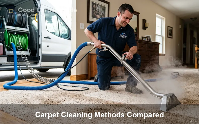
For detailed analysis of when replacement becomes the superior economic and health decision compared to restoration, see our guide at when to replace carpet . For a full comparison of structural drying and hot-water extraction cleaning as post-loss interventions, review carpet cleaning methods compared .
Understanding how to properly steam clean carpet in minor moisture events — those well below IICRC S500 Class 1 thresholds — helps clarify the fundamental difference between cleaning technology and structural drying technology: see how to steam clean carpet .
Drying window recap: the numbers that matter
- 24 hours: Maximum time before Category 1 loss escalation risk at > 68°F
- 48 hours: Near-certain mold colonization in saturated porous assemblies at typical indoor temperatures
- 6–8 feet: Air mover spacing for proper boundary layer disruption coverage per IICRC S500 displacement theory
- 45 degrees: Wall angle for helical airflow pattern across carpet surface
- ≤ 15% MC: Carpet moisture content dry standard at project completion
- ≤ 12% MC: Wood subfloor moisture content dry standard
- 80%: Maximum safe continuous electrical load on any circuit (OSHA 29 CFR 1910.304)
- 5 mA: GFCI trip threshold — mandatory in all wet restoration environments
- 30 GPP: LGR dehumidifier effective lower limit — conventional units stall at 45–55 GPP
Water damage is measured in hours. Every equipment decision made in the first four hours determines whether a carpet returns to service or goes to the dumpster. Deploy correctly, monitor rigorously, and document completely.